Choosing the right X Ray Intensifier in 2026 requires more than comparing resolution numbers. Buyers must examine system compatibility, image brightness, input field size, distortion, and long-term service support. A device may look impressive in a brochure. It may still perform poorly with an aging generator or unsuitable camera interface.
This guide reviews major X Ray Intensifier types for hospitals, imaging centers, mobile C-arm teams, and equipment distributors. It considers conventional fluoroscopy units, compact surgical models, replacement assemblies, and application-specific configurations. Practical purchasing experience shows that connector design, mounting space, cooling requirements, and calibration access often influence results more than expected.
Small details matter.
A reliable evaluation should combine manufacturer specifications, independent testing, maintenance records, and user feedback from comparable clinical environments. Buyers should request documented performance data, warranty terms, radiation safety information, and compatibility confirmation before placing an order. Regulatory approvals and local service capability also deserve careful review.
Not every stated advantage survives daily use. A higher resolution rating may not produce clearer images when alignment is poor or the display is outdated. Similarly, a lower-cost replacement may create hidden expenses through installation delays, recalibration, or limited parts availability. This guide therefore emphasizes measurable performance, total ownership cost, supplier credibility, and realistic workflow demands. The best choice is not always the newest model. It is the option that remains dependable during repeated examinations, fits the existing system, and can be supported throughout its expected service life.
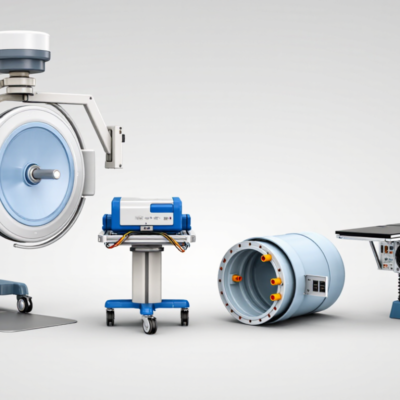
X-ray intensifiers convert low-energy X-rays into visible light for real-time imaging. Their operation follows several precise stages. An input phosphor absorbs X-rays and produces light. A photocathode changes that light into electrons. Electrostatic lenses focus the electrons toward the output phosphor. The output phosphor then creates a brighter image for the camera system.
Brightness gain combines minification gain and flux gain. Minification gain comes from compressing a large input image onto a smaller output screen. Flux gain increases light through electron acceleration. This process supports fluoroscopy with relatively low exposure settings.
However, lower exposure does not mean unlimited safety. Patient size, pulse rate, filtration, and clinical purpose still affect image quality.
Buyers should compare single-field and multi-field intensifiers carefully. Multi-field designs offer selectable viewing areas, such as large, medium, and small fields. A smaller field usually improves detail but reduces viewing coverage.
Watch for pincushion distortion, S-distortion, veiling glare, and edge blur. These effects can hide small anatomical details. They matter.
A reliable evaluation includes uniformity testing, spatial resolution checks, and inspection for image lag. Ask for service records and measured performance data. Do not depend only on catalogue values.
In practice, aging components may perform differently from their original specifications. That is an uncomfortable but important limitation. Detector compatibility, operating distance, maintenance access, and replacement costs also deserve close attention.
2026 Best X-Ray Intensifier Types for Buyers?
Major X-Ray Intensifier Types and Their Structural Differences
An X-ray image intensifier converts low-level X-ray exposure into a brighter visible image. Its structure includes an input window, cesium iodide layer, photocathode, electrostatic focusing lenses, and output phosphor. Each part affects contrast, resolution, and image distortion. The input screen is usually curved. This design helps limit peripheral distortion, but it can reduce accuracy near the edges.
Single-field intensifiers use one fixed viewing diameter. They have a simpler internal focusing structure and suit dedicated imaging tasks. Dual-field models provide two selectable diameters, commonly a larger field for positioning and a smaller field for detail. Triple-field models add another magnification level. Smaller fields improve apparent resolution, but they also reduce the visible anatomy and may require more precise positioning.
Buyers should compare the tube diameter, field switching method, input material, and spatial resolution. A larger intensifier can cover more anatomy, yet it may increase geometric distortion. Smaller formats show finer structures but demand careful alignment. In practical inspections, check for lag, veiling glare, uneven brightness, and edge distortion. Ask for test images, not only catalog figures. Numbers can mislead. A high resolution rating may still produce weak clinical detail when the tube is aged, poorly calibrated, or matched with unsuitable optics. No type fits every workflow.
A buyer-oriented comparison of conventional X-ray image-intensifier configurations, their internal structures, operating characteristics, and typical fluoroscopic applications.
| Type | Primary Structural Design | Input and Output Components | Typical Field Configuration | Main Advantages | Main Limitations | Typical Buyer Applications |
|---|---|---|---|---|---|---|
| Single-Field Image Intensifier | One fixed input field is supported by a single electrostatic focusing arrangement inside the evacuated tube. The complete input area is used without electronic field switching. | Usually uses a cesium iodide needle-crystal input phosphor, a photocathode, electrostatic focusing electrodes, an accelerating anode, and a zinc-cadmium-sulfide output phosphor. | One fixed field Common formats include approximately 6-inch, 9-inch, or 12-inch nominal input diameters, depending on the system. |
Simple operating architecture, predictable geometry, and no field-selection mechanism. It can be suitable where one consistent viewing area is sufficient. | Limited flexibility for magnification and collimation. A fixed field may be less efficient for procedures requiring both broad anatomical coverage and detailed small-area imaging. | Basic fluoroscopy, legacy radiographic-fluoroscopic rooms, and applications with stable field-of-view requirements. |
| Dual-Field Image Intensifier | Two selectable electrostatic focusing modes use different portions of the input screen. The smaller mode magnifies the central image region electronically. | Shares the same vacuum-tube architecture, but includes focusing-electrode control designed for two operating fields. | Large field Small field Often described by paired nominal fields such as 9/6 inches or 6/4.5 inches. |
Provides a practical balance between anatomical coverage and improved detail during targeted imaging. It is more versatile than a single-field design. | The smaller field covers less anatomy and can reduce dose efficiency if repeatedly selected for large regions. Resolution and noise also depend on the system’s operating settings. | General fluoroscopy, gastrointestinal studies, pain procedures, and systems requiring occasional electronic magnification. |
| Triple-Field Image Intensifier | Three selectable electron-optics configurations focus different input regions onto the output screen. Field selection changes the effective viewing area and magnification. | Uses a multi-mode electrostatic lens assembly in the vacuum envelope, with the standard input phosphor, photocathode, and output phosphor structure. | Large field Medium field Small field Examples may include approximately 12/9/6 inches or 9/6/4.5 inches. |
Offers broad coverage, intermediate framing, and a higher-magnification mode in one tube. It supports varied procedures without changing the detector assembly. | More complex control and calibration requirements. Small-field operation may increase patient dose because automatic exposure control can raise output to maintain image brightness. | Interventional fluoroscopy, cardiovascular imaging, orthopedic procedures, and rooms serving multiple procedure types. |
| High-Resolution Image Intensifier | Optimized electron optics, input-screen construction, and output coupling are designed to preserve fine detail, usually through a smaller effective field or dedicated magnification mode. | Typically uses finely structured cesium iodide crystals and a high-quality photocathode-to-output-screen optical chain. The exact performance depends on tube design and camera or sensor coupling. | Small or selectable field Often used in a dedicated magnification range rather than as a full-room field. |
Improved visualization of small anatomy, guidewires, catheters, bone margins, and other high-contrast structures. | Smaller coverage, potentially higher patient dose during magnification, and greater sensitivity to alignment, focal-spot size, motion, and display processing. | Fine-detail fluoroscopy, vascular work, interventional procedures, and selected orthopedic or pain-management examinations. |
| High-Contrast Image Intensifier | Uses design and operating choices intended to improve separation between adjacent signal levels. Performance is affected by the input phosphor, electron optics, scatter conditions, and image-processing chain. | Generally retains the conventional vacuum tube, cesium iodide input phosphor, photocathode, focusing electrodes, and output phosphor; contrast is not determined by one component alone. | Usually selectable May be available in single-, dual-, or triple-field configurations. |
Can make boundaries and high-contrast objects easier to distinguish, particularly when scatter control and exposure settings are well managed. | Higher contrast does not necessarily mean higher spatial resolution. Noise, veiling glare, lag, scatter, and geometric distortion can still affect diagnostic quality. | Procedures where visibility of contrast-filled vessels, bone edges, or devices is more important than maximum low-contrast performance. |
| Compact or Miniature Image Intensifier | A smaller vacuum tube and smaller input diameter are used to reduce detector size and mechanical load. The internal operating principle remains that of an electrostatic X-ray image intensifier. | Uses the same basic sequence of input phosphor, photocathode, electron focusing, acceleration, and output phosphor, but in a reduced physical package. | Small fixed field Commonly selected when limited coverage is acceptable. |
Lower weight, easier integration into compact C-arms or specialized equipment, and improved access around small anatomical regions. | Restricted anatomical coverage, less flexibility for large patients or broad examinations, and possible limitations in spatial resolution or brightness depending on the design. | Mobile C-arms, extremity imaging, operating-room procedures, dental or maxillofacial fluoroscopy, and other space-constrained systems. |
| Flat-Panel Detector Not an Image Intensifier |
Uses a solid-state detector panel rather than a vacuum tube. A scintillator converts X-rays to light, and an active-pixel array converts the light into electrical signals. | Common indirect-conversion designs use cesium iodide or another scintillator over an amorphous-silicon photodiode array. Direct-conversion designs use a photoconductor such as amorphous selenium. | Fixed panel area Electronic cropping can change displayed framing but does not create the same electron-optical magnification fields as an image intensifier. |
No traditional pincushion or S-distortion, no vacuum-tube wear, large rectangular coverage, and generally consistent geometry across the active area. | May have higher acquisition and replacement costs. Image lag, dead pixels, detector damage, readout limits, and dose-efficiency characteristics vary by panel technology. | New fluoroscopy installations, digital radiography-fluoroscopy rooms, interventional suites, and systems prioritizing geometric accuracy. |
Buyer note: Nominal field sizes, resolution, dose performance, lag, distortion, and usable magnification vary by tube design and complete imaging system. When comparing equipment, evaluate the image-intensifier tube together with the X-ray generator, focal spot, automatic exposure control, optical coupling, camera or digital processor, collimation, and service condition.
Choosing an X-ray image intensifier in 2026 requires more than comparing resolution figures. Buyers should examine conventional, compact, and high-resolution configurations against the procedure’s real workload. For mobile fluoroscopy, a smaller unit may improve positioning, while a large input field supports broader anatomy. That trade-off is easy to miss. Ask for measured conversion factor, modulation transfer function, detective quantum efficiency, lag, and geometric distortion. Request test images at several dose levels, not one ideal setting. Clinical engineers should also verify field-size switching, output stability, and compatibility with the existing generator and display.
Image quality is not simply sharpness. Low noise, stable contrast, and predictable performance during motion often matter more in daily fluoroscopy. Compare spatial resolution at the center and edges of the image. Check whether pincushion distortion or veiling glare could hide small structures. A controlled phantom test is useful, but it cannot reproduce every patient size or clinical angle. That limitation deserves honest discussion. Ask clinicians to review stored cases under realistic operating conditions.
Safety comparisons should include patient dose, operator exposure, and failure behavior. Look for pulsed operation, automatic exposure control, dose-area monitoring, last-image hold, and clear alarm functions. Shielding and distance still matter. An intensifier that produces a bright image at unnecessary dose is not a strong purchase. Procurement teams should confirm service intervals, calibration records, and training responsibilities before signing. Ideally, test the unit in the actual room. Bench data can mislead. A rushed evaluation may reward impressive images while overlooking workflow delays, aging components, or difficult cleaning.
Choosing the best X-ray intensifier depends on the imaging system, not on size alone. A standard circular intensifier can support fluoroscopy, gastrointestinal studies, and older radiographic systems. Its cesium iodide input screen converts X-rays efficiently, producing a bright image with relatively low exposure. However, image quality may decline near the edges. This matters during wide-field examinations.
Mobile C-arms often use compact intensifiers for orthopedic procedures and pain management. Smaller units provide easier positioning around the patient and surgical table. Larger formats suit vascular imaging and extended anatomical views. In angiography, high contrast and stable resolution are essential for displaying vessels, guidewires, and contrast movement. A buyer should check distortion, spatial resolution, input field sizes, and dose performance under realistic operating conditions.
Marketing figures can look impressive. Clinical testing is better. Dental and specialty imaging systems may require miniature intensifiers with precise geometry. Their limited field can improve positioning in confined spaces, but it may not suit broader examinations. Compatibility also includes optical coupling, camera interfaces, mounting space, and service availability. Intensifiers are proven technology, yet many new systems use flat-panel detectors. That does not make intensifiers useless. It makes comparison more important. I have seen buyers focus too heavily on resolution and overlook lag, maintenance access, or operator workflow. A simple phantom test may reveal more than a long specification sheet. Mistakes still happen.
Choosing an X-ray intensifier in 2026 starts with the clinical task, not the catalog label. Compare standard, high-resolution, and compact intensifiers by field size, spatial resolution, contrast, distortion, and conversion efficiency. A smaller field may sharpen orthopedic detail, while a larger field supports broader fluoroscopic views. Ask for measured data, not marketing language.
Dose performance deserves careful checking. The UNSCEAR 2020/2021 report states that medical exposure represents about 95% of radiation exposure from human-made sources. Request dose-area-product results, pulsed-fluoroscopy performance, and image quality at low exposure settings. Also review lag, veiling glare, and brightness uniformity. These details affect moving anatomy and repeat examinations. They are easy to overlook.
Compatibility can decide the purchase. Verify mounting dimensions, optical output, generator interfaces, software communication, and table clearance before signing. Confirm calibration procedures and local service response times. Request acceptance-test records from comparable installations. A lower purchase price can become expensive when replacement parts are slow or integration is poor. The IAEA recommends equipment quality assurance, routine performance testing, and dose optimization throughout the system’s working life. One practical warning: published resolution may use ideal test objects. Real patients are less cooperative. Test the intensifier with your own workflow, typical pulse rates, and representative clinical tasks.