
Services
2026 Best UV Image Intensifiers for Global Buyers
The 2026 Best UV Image Intensifiers guide examines practical choices for laboratories, inspection teams, and research facilities worldwide. A Uv Image Intensifier can reveal weak ultraviolet signals that standard cameras often miss. This capability matters in spectroscopy, semiconductor inspection, flame studies, and controlled scientific experiments. Performance depends on more than gain ratings. Photocathode sensitivity, wavelength range, resolution, noise, and operating stability also deserve close attention.
Real purchasing decisions often begin with a dark test room, calibrated ultraviolet sources, and several hours of continuous operation. Buyers should compare measurable results, not attractive brochures. A device showing strong sensitivity at 200 nanometers may perform differently near 400 nanometers. Small differences can affect image clarity, maintenance costs, and project outcomes. However, laboratory conditions rarely match marketing demonstrations perfectly. That limitation deserves honest consideration.
This overview applies an evidence-led approach. It considers manufacturer documentation, independent testing, warranty terms, technical support, and user feedback. Compliance requirements may vary between countries, industries, and research institutions. Buyers should confirm product certification, import rules, electrical standards, and end-use requirements before ordering. Authorized distributors can provide safer documentation and clearer after-sales support. Prices also require context, because cooling systems, lens compatibility, software, and replacement components can change total ownership costs.
There is no universal winner. A compact model may suit field inspection, while a cooled system may better serve extended laboratory imaging. Some specifications remain difficult to compare consistently across brands. This guide highlights those gaps rather than hiding them. Readers can therefore build a shortlist based on verified performance, responsible sourcing, and clearly defined application needs.
UV Image Intensifiers: Definition, Purpose, and Core Operating Principles
2026 Best UV Image Intensifiers for Global Buyers
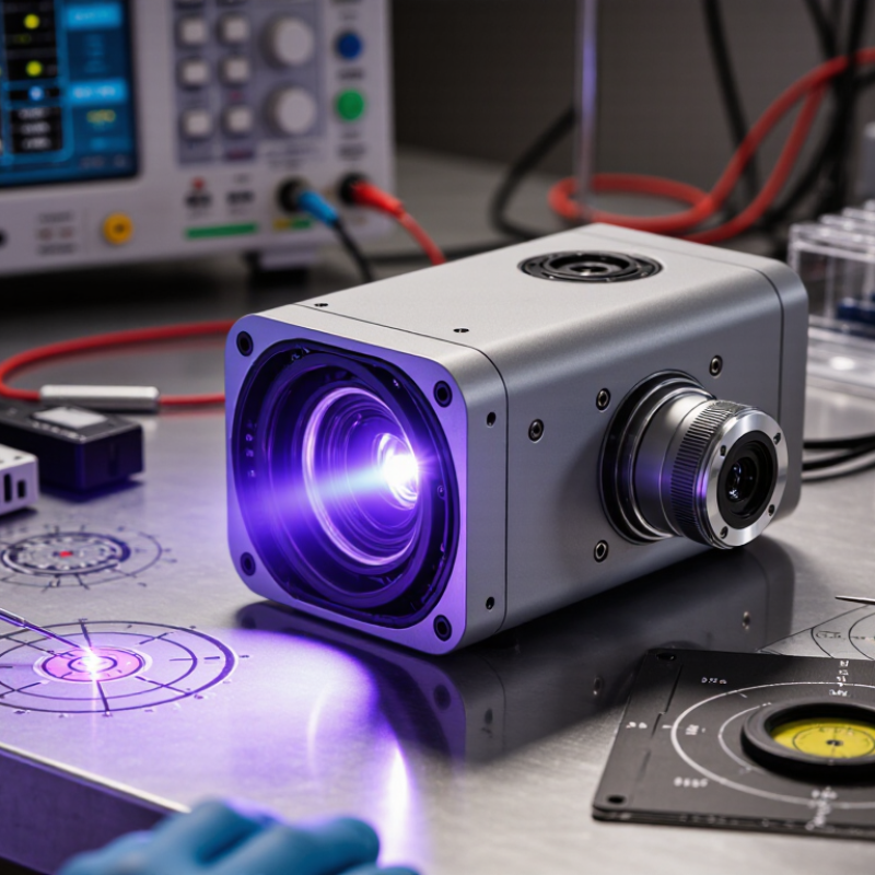
UV image intensifiers amplify weak ultraviolet radiation into a visible image. A photocathode first converts UV photons into electrons. A microchannel plate multiplies those electrons. A phosphor screen then recreates the image for a camera or display. The conversion is fast. This architecture supports flame monitoring, corona inspection, scientific imaging, and low-light industrial measurement.
Most systems target ultraviolet wavelengths between 200 and 400 nanometers. Solar-blind models focus mainly on approximately 240–280 nanometers, where sunlight is strongly absorbed by the atmosphere. Not every tube qualifies. Buyers should verify photocathode sensitivity, gain, signal-to-noise ratio, resolution, and operating lifetime under real conditions. According to a 2024 Grand View Research assessment, the global UV sensor market was valued at roughly USD 1.4 billion in 2023, with annual growth projected above 8% through 2030. That report covers sensors broadly, not image intensifiers, but it reflects expanding demand for precise UV detection. A 2024 MarketsandMarkets analysis also identified industrial inspection and scientific instrumentation as important UV application areas. The practical lesson is less glamorous: higher gain does not always mean better images. Excess gain can increase noise and obscure small features. Optical filters, calibration records, and stable high-voltage control matter just as much. Specifications can mislead. Field testing remains necessary.
2026 Best UV Image Intensifiers for Global Buyers - UV Image Intensifiers: Definition, Purpose, and Core Operating Principles
| Configuration or Selection | Typical Spectral Coverage | Main Photocathode or Input Technology | Typical Performance Range | Primary Applications | Key Advantages | Main Limitations |
|---|---|---|---|---|---|---|
| Solar-blind UV intensifier | Approximately 200–280 nm, depending on photocathode design and filtering | Wide-bandgap photocathodes, commonly based on cesium telluride or related alkali telluride materials | High rejection of visible sunlight; typical gain from approximately 103 to 106; resolution commonly about 20–60 line pairs/mm | Corona detection, high-voltage inspection, electrical equipment monitoring, flame detection, and solar-blind imaging | Low visible-background response and strong contrast in daylight UV measurements | Limited spectral range; performance can vary significantly with solar-blind filter and photocathode selection |
| Deep-UV intensifier | Approximately 115–200 nm for suitable vacuum-UV or deep-UV configurations | Ultraviolet-sensitive photocathodes such as cesium iodide, often used with specialized entrance windows | High sensitivity in short-wave UV; resolution commonly about 15–50 line pairs/mm; vacuum-UV transmission must be considered | Vacuum-UV spectroscopy, semiconductor process monitoring, combustion research, and laboratory diagnostics | Access to wavelengths below the normal transmission range of ordinary optical glass | Requires compatible window materials, optical components, and controlled environmental conditions; air absorption may be significant |
| Near-UV intensifier | Approximately 280–400 nm | UV-sensitive photocathodes selected for near-UV response; some designs may extend toward visible wavelengths | Typical gain from approximately 103 to 105; resolution commonly about 25–65 line pairs/mm | Fluorescence imaging, forensic inspection, ultraviolet photography, biological research, and industrial quality control | Good compatibility with common UV optics and relatively straightforward system integration | Visible-light leakage can reduce contrast unless optical filtering and shielding are properly designed |
| MCP-based high-gain intensifier | Determined mainly by the photocathode; commonly near-UV to solar-blind UV | UV photocathode coupled to a microchannel plate (MCP) electron multiplier | Adjustable or fixed gain commonly around 104–106; fast response can reach nanosecond-scale gating in specialized systems | Low-light UV imaging, pulsed-laser diagnostics, high-speed combustion studies, and transient event recording | High gain, fast gating, and strong performance for weak or short-duration UV events | Possible gain saturation, reduced lifetime under intense exposure, image noise, and higher system cost |
| Proximity-focused intensifier | Commonly approximately 180–400 nm, depending on the photocathode and window | Photocathode, MCP, and phosphor arranged with short electron travel distances | High spatial fidelity; typical resolution about 25–70 line pairs/mm; low geometric distortion compared with many electrostatic designs | Scientific imaging, spectroscopy, microscopy, and compact camera modules | Compact construction, low distortion, and good coupling to fiber-optic or lens-based camera systems | Performance depends strongly on photocathode uniformity, MCP quality, and output-coupling design |
| Fiber-optic output intensifier | Determined by the input photocathode and system filter | UV photocathode and MCP with a fiber-optic faceplate at the output | Typical resolution about 20–60 line pairs/mm; efficient coupling to scientific cameras; gain commonly 103–106 | Digital UV imaging, machine vision, microscopy, spectroscopy, and remote measurement systems | Efficient, compact coupling to cameras and reduced optical alignment complexity | Fiber faceplate pattern, coupling losses, and camera compatibility must be evaluated before purchase |
| Phosphor-screen visual output | Determined by the UV photocathode; visible output is typically green or blue-green | UV photocathode, electron multiplier, and visible phosphor screen such as P43 or P46-class phosphors | Direct viewing is possible; persistence ranges from short-persistence to longer-persistence formats depending on phosphor selection | Inspection instruments, field observation, alignment, and visual confirmation of UV events | Simple human-readable output and convenient real-time observation | Lower quantitative accuracy than calibrated digital output; phosphor persistence may blur fast events |
| Gated UV intensifier | Usually approximately 180–400 nm, subject to photocathode selection | UV photocathode with electrically controlled photocathode or MCP gating | Gate widths can range from microseconds to nanoseconds in specialized designs; timing performance depends on the driver and system architecture | Laser-induced fluorescence, pulsed plasma imaging, combustion diagnostics, and time-resolved spectroscopy | Suppresses background light and freezes rapidly changing UV phenomena | Requires precise triggering, suitable pulse electronics, and careful synchronization with the source |
| Radiation-tolerant configuration | Application-specific; commonly selected for near-UV or solar-blind operation | UV photocathode and intensified architecture designed for elevated radiation or harsh operating environments | Performance is application-specific; lifetime depends on total dose, dose rate, operating temperature, and gain setting | Space instrumentation, nuclear facilities, plasma research, and harsh industrial inspection | Can provide imaging where ordinary sensors may suffer rapid degradation | Requires verified radiation data; tolerance cannot be inferred from gain or resolution alone |
| Dimension | Operating Principle | What to Compare | Buyer Relevance |
|---|---|---|---|
| Photon conversion | The photocathode absorbs UV photons and releases photoelectrons through the photoelectric effect. | Quantum efficiency, spectral response, uniformity, and wavelength cut-off | Determines how effectively weak UV radiation is converted into a usable electron signal. |
| Electron multiplication | Electrons enter MCP channels and generate secondary electrons through repeated impact multiplication. | Gain, gain uniformity, saturation behavior, noise, and lifetime | Controls image brightness and sensitivity, especially under low-light or short-exposure conditions. |
| Electron focusing | Electric fields guide the amplified electron pattern from the input surface to the output screen or sensor. | Spatial resolution, distortion, edge performance, and geometric fidelity | Important for measurement, pattern recognition, microscopy, and precision inspection. |
| Visible image formation | A phosphor screen converts amplified electrons into visible photons, commonly in a green or blue-green emission band. | Phosphor type, brightness, persistence, spectral output, and screen uniformity | Influences visual observation, motion sharpness, camera sensitivity, and frame-rate requirements. |
| Digital coupling | The output image is transferred to a camera through a fiber-optic faceplate, relay lens, or direct sensor coupling. | Coupling efficiency, field of view, distortion, interface size, and sensor compatibility | Determines system throughput, mechanical integration, and final image quality. |
| Temporal control | Electrical gating turns the photocathode or MCP on and off to select precise time windows. | Gate width, repetition rate, delay, jitter, trigger interface, and extinction ratio | Essential for pulsed UV sources, laser diagnostics, and suppression of unwanted background radiation. |
| Optical filtering | Band-pass, short-pass, or solar-blind filters restrict unwanted UV and visible wavelengths before they reach the photocathode. | Transmission band, out-of-band rejection, angle sensitivity, and filter durability | Improves contrast and prevents visible-light contamination or photocathode overload. |
| Environmental suitability | Tube and housing materials must maintain vacuum integrity and stable operation across the intended temperature, humidity, vibration, and radiation range. | Operating temperature, storage temperature, shock, vibration, humidity, vacuum quality, and radiation data | Determines reliability in field, aerospace, laboratory, and industrial environments. |
| Safety and compliance | UV sources, high-voltage supplies, vacuum devices, and export-controlled technologies may require specific handling and documentation. | Electrical safety, UV exposure controls, customs documentation, conformity assessment, and end-use requirements | Helps global buyers reduce installation delays, regulatory risk, and unsafe operation. |
Related Posts
-
How to Enhance Night Vision Using Mcp Image Intensifiers
-

Top Digital Image Intensifier Tips for Global Buyers?
-
What Is Image Intensifier Night Vision and How Does It Work?
-
Ultimate Guide to Sourcing Microchannel Plate Image Intensifiers for Enhanced Imaging Solutions
-

10 Essential Image Intensifier Technologies Transforming Global Procurement Trends
-

Understanding the Functionality and Applications of Mobile Image Intensifiers in Modern Technology