
Services
How to Choose a Valve Position Monitor in 2026?
Choosing a Valve Position Monitor in 2026 requires more than comparing prices and product brochures. The right device must show whether a valve is open, closed, or moving unexpectedly. It should also provide dependable feedback in the actual operating environment. Dust, vibration, moisture, heat, and corrosive chemicals can quickly expose weak designs.
A practical evaluation begins with valve type, actuator movement, switching accuracy, and communication requirements. Rotary and linear valves may need different mounting systems. Confirm the monitor’s sensing range before installation. A few millimeters of misalignment can create unreliable signals. Check enclosure ratings, operating temperature, diagnostic functions, and cable connections. For modern plants, smart communication protocols may simplify maintenance, but they can also increase configuration work. Simple is sometimes safer.
Reliability should be proven through technical documentation, application records, and realistic testing. Ask whether the manufacturer provides calibration guidance, replacement parts, and responsive engineering support. A device that performs well in a clean workshop may struggle beside a vibrating pump or outdoor pipeline. Site trials can reveal these differences. They are worth the effort.
No selection guide is perfect. Budget pressure may favor a basic switch, while safety-critical processes may require advanced diagnostics and certified performance. The best Valve Position Monitor balances accuracy, durability, integration, and lifecycle cost. Reviewers should document their assumptions and revisit them after installation. Small oversights matter. A visible status light, secure bracket, and clear fault signal can prevent confusion during a demanding maintenance shift.
What Is a Valve Position Monitor and How Does It Work?
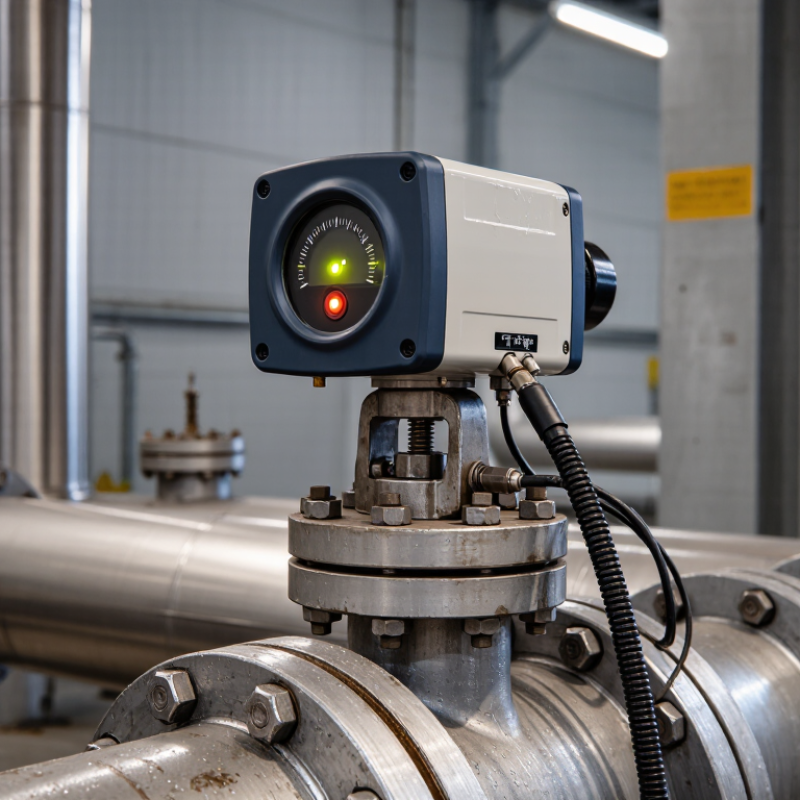
A valve position monitor is a device that reports whether an industrial valve is open, closed, or somewhere between. It connects the valve’s mechanical movement with a control system, giving operators visible and electrical feedback. Inside, a cam, sensor, or rotary mechanism follows the valve shaft. When the shaft turns, the monitor changes its signal.
Common models use limit switches, proximity sensors, or continuous position transmitters. A limit switch confirms a defined endpoint, such as fully closed. A transmitter provides a changing signal, which helps track partial opening and movement speed. In a plant room, this information may appear on a control screen while a small indicator shows the local position. The best choice depends on valve type, travel range, temperature, moisture, and required accuracy.
Installation experience often reveals small weaknesses. A poorly aligned actuator can make a healthy monitor report the wrong position. Vibration may loosen mounting hardware over time. For this reason, technicians should test both end positions and compare the signal with the valve’s actual movement. A protective enclosure matters in dusty or wet locations. Communication protocols also deserve attention, because a monitor must match the control system’s input. No device is perfect. Calibration can drift, and a “closed” signal may hide mechanical damage unless inspections continue. During selection, reliability records, service access, and clear wiring diagrams deserve as much attention as the purchase price.
How to Choose a Valve Position Monitor in 2026? - What Is a Valve Position Monitor and How Does It Work?
| Selection Dimension | Available Option | How It Works | Typical Output or Rating | Best-Fit Application | Important Consideration |
|---|---|---|---|---|---|
| Feedback technology | Mechanical limit switches | A cam or actuator mechanically changes the switch contact when the valve reaches a preset position. | Discrete open/closed contact signals | Basic open-or-closed monitoring and simple control systems | The contact arrangement, switching load, and mechanical adjustment range must match the control circuit. |
| Feedback technology | Inductive proximity sensors | A metal target is detected without physical contact as it moves into the sensor’s sensing field. | Discrete electronic switching signal | Frequent cycling, reduced mechanical wear, and compact valve assemblies | Verify sensing distance, target material, supply voltage, and compatibility with the input module. |
| Feedback technology | Magnetic or reed sensors | A magnetic field operates a sensor when a magnet attached to the actuator reaches the defined position. | Discrete switching signal | Non-contact position detection in enclosed or compact mechanisms | Strong external magnetic fields and the required switching distance can affect installation suitability. |
| Feedback technology | Potentiometric position sensor | A rotating electrical resistance changes continuously with the valve shaft position. | Variable resistance or voltage signal | Continuous position indication where a compatible analog input is available | Mechanical wear, electrical noise, and signal scaling should be evaluated. |
| Feedback technology | Non-contact rotary sensor | Magnetic, optical, or other electronic sensing tracks shaft rotation without a rubbing contact. | Discrete, analog, or digital position data, depending on the design | High-cycle service and applications requiring reduced mechanical wear | Check temperature limits, resolution, electrical interface, and resistance to vibration. |
| Position information | Open/closed indication | The monitor confirms whether the valve has reached one or both defined end positions. | Two-state status | On/off valves, isolation valves, and interlock functions | It does not normally show the exact intermediate opening percentage. |
| Position information | Continuous position feedback | The sensor converts shaft or actuator travel into a continuously changing electrical signal. | Commonly a 4–20 mA analog signal | Modulating valves and process control loops | Confirm loop power, load resistance, scaling, accuracy, and cable length requirements. |
| Actuator compatibility | Quarter-turn actuator | The monitor follows the rotary movement of actuators commonly used with ball, butterfly, and plug valves. | Typical travel: approximately 90° for many on/off designs | Rotary on/off valve assemblies | Verify shaft dimensions, mounting pattern, travel angle, and available adjustment range. |
| Actuator compatibility | Linear actuator | The monitor detects stem travel or converts linear movement into an electrical position signal. | Travel-dependent discrete or analog signal | Globe, gate, diaphragm, and other linear-motion valves | The stem travel range, mounting arrangement, and alignment are critical. |
| Electrical interface | Dry contact | The monitor provides an electrically isolated contact that is interpreted by an external control circuit. | Normally open, normally closed, or changeover contact | PLC inputs, relay logic, and simple monitoring circuits | Check maximum voltage, current, contact material, and whether the circuit is AC or DC. |
| Electrical interface | Powered electronic output | An internal electronic circuit produces a defined signal using an external or loop power supply. | Discrete voltage, current, or digital communication signal | Automated systems requiring diagnostic or continuous data | Confirm supply voltage, current consumption, signal type, polarity, and control-system compatibility. |
| Environmental protection | IP65 enclosure | The enclosure is dust-tight and protected against water jets from any direction when correctly installed. | Ingress Protection rating: IP65 | Indoor or outdoor locations exposed to dust and rain | IP protection depends on correct cable glands, covers, seals, and installation practices. |
| Environmental protection | IP67 enclosure | The enclosure is dust-tight and protected against temporary immersion under defined test conditions. | Ingress Protection rating: IP67 | Washdown areas or locations subject to temporary flooding | IP67 does not automatically mean protection against continuous underwater operation or high-pressure cleaning. |
| Hazardous-area suitability | Ordinary industrial area | The monitor is intended for locations without a classified explosive atmosphere. | Non-hazardous-area installation | General water, HVAC, manufacturing, and utility systems | Do not install in a classified area unless the device has the required certification and installation method. |
| Hazardous-area suitability | Certified hazardous-area model | The monitor is designed and certified for specified explosive-atmosphere zones or divisions under stated conditions. | Certification depends on the applicable jurisdiction and protection method | Chemical, oil and gas, pharmaceutical, and other classified process areas | Match the certificate, gas or dust group, temperature class, zone, wiring method, and ambient temperature. |
| Operating conditions | Standard industrial temperature | The monitor operates within the temperature range stated in its technical documentation. | Use the manufacturer’s specified ambient range; no universal range applies | Typical indoor and outdoor industrial installations | Consider enclosure heating, solar exposure, process heat, cold starts, and temperature cycling. |
| Maintenance requirement | Contact-based mechanism | Mechanical parts and contacts physically move or engage to create the feedback signal. | Periodic inspection may be required, depending on duty cycle | Applications prioritizing simple troubleshooting and low initial complexity | Vibration, wear, corrosion, and incorrect cam adjustment can affect reliability. |
| Diagnostic capability | Basic status only | The control system receives the valve state but little or no internal device information. | Open/closed or position signal | Straightforward installations with local troubleshooting | Additional equipment may be needed to identify wiring faults, sensor failure, or incomplete travel. |
| Diagnostic capability | Advanced electronic diagnostics | The monitor can provide additional information such as signal status, configuration data, or detected faults. | Depends on the selected communication protocol | Large plants, remote assets, and predictive-maintenance programs | Verify protocol support, integration software, cybersecurity requirements, and technician training. |