
Services
How to Choose a C Arm Image Intensifier in 2026
Choosing a C Arm Image Intensifier in 2026 means balancing image quality, radiation management, workflow, and long-term serviceability. The technology remains relevant where existing equipment, budgets, or clinical tasks favor image intensifiers over flat-panel detectors. But the label alone tells little. A specification sheet can look reassuring while hiding uneven performance across magnification modes.
Professional guidance helps frame the decision. The IAEA’s Safety Standards Series No. SSG-46, Radiation Protection and Safety in Medical Uses of Ionizing Radiation, addresses radiation protection and equipment quality assurance. NCRP Report No. 168, Radiation Dose Management for Fluoroscopically-Guided Interventional Medical Procedures, likewise emphasizes dose management in fluoroscopy. Neither report ranks commercial systems. Both make practical testing essential. Measure image quality and dose under representative clinical conditions, rather than relying only on brochure claims.
Start with the work performed in your room. Compare field-of-view options, image intensifier size, spatial resolution, contrast, distortion, and performance during magnification. Check whether the monitor, generator, table, and image-recording workflow fit your existing setup. Ask for documented acceptance-test results and service-response details. Also review parts availability; an excellent image is less useful when repairs take weeks. Small details matter. A busy orthopedic room and a mobile pain clinic may need different configurations. I would not treat one attractive resolution figure as a verdict. It is tempting, but incomplete. A careful comparison should connect verified performance with real procedures, staff experience, and the cost of keeping the system dependable.
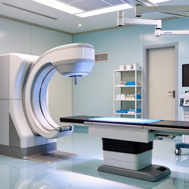
Understand C-Arm Image Intensifier Types and Core Components
Choosing a C-arm image intensifier starts with understanding the detector type. Traditional image intensifiers use an input phosphor, photocathode, electron optics, and output phosphor to convert X-rays into visible light. Flat-panel detectors instead use a digital detector panel, often offering a more uniform image and less geometric distortion. European Commission Radiation Protection No. 162 lists 50 cd/m² per μGy/s as a minimum image-intensifier conversion-factor criterion. Treat this as a technical reference, not a substitute for local acceptance testing. Small details matter.
The core components affect both image quality and workflow. The input phosphor receives X-rays; the photocathode converts light into electrons. Electron optics focus those electrons, while the output phosphor creates an image for the camera or optical coupling system. Check field-of-view options, image brightness, edge distortion, and compatibility with the C-arm’s camera and display chain. During inspection, compare image uniformity across the field and look for fading, blemishes, or sluggish brightness changes. I still find it easy to overlook the coupling optics. A sound detector can produce disappointing images when those parts are poorly aligned or degraded. Review service records and acceptance measurements before choosing a replacement.
How to Choose a C Arm Image Intensifier in 2026: Understand Types and Core Components
| Category | Type or Component | What It Does | Selection Considerations |
|---|---|---|---|
| Input field size | Large field of view | Captures a wider area of anatomy in one image. Image-intensifier input sizes are commonly specified in inches; available sizes vary by system. | Consider it when broad anatomical coverage is important. Check the usable field of view and whether it suits the procedures and patient population. |
| Input field size | Multiple-field or multi-mode intensifier | Provides selectable field sizes, often using electronic magnification modes that image a smaller central area of the input phosphor. | Compare the available field-size modes, transition controls, and image performance in each mode. Smaller magnification fields can increase patient dose when automatic brightness control compensates for reduced signal. |
| Image-intensifier mode | Magnification mode | Uses a smaller portion of the input field to make the anatomy appear larger on the output image. | Useful when finer anatomical detail is needed. Review dose behavior, image noise, and the system’s dose-management features for each magnification setting. |
| Core component | Input window and input phosphor | The input side admits X-rays. The input phosphor, commonly made with cesium iodide, converts X-ray energy into visible light. | Ask for documented image-quality and durability information. The input assembly’s condition can affect image quality, so inspect service history and image uniformity. |
| Core component | Photocathode | Converts light from the input phosphor into electrons. | Its performance contributes to conversion efficiency and image quality. Compare specifications and service condition rather than relying on component age alone. |
| Core component | Electrostatic focusing lenses | Guide and focus electrons from the photocathode toward the output phosphor. | Stable focusing is important for image sharpness and geometry. Evaluate images across the available field sizes and check for distortion or focus nonuniformity. |
| Core component | Anode and high-voltage supply | The anode accelerates electrons toward the output phosphor; the high-voltage supply supports the intensifier’s electron-acceleration system. | Review electrical safety, system condition, and maintenance records through qualified service personnel. |
| Core component | Output phosphor | Converts the accelerated electron image back into visible light for capture by the camera system. | Check output brightness, image uniformity, and compatibility with the C-arm’s camera and image-processing chain. |
| Image quality | Resolution and contrast | Describe how well the system depicts small structures and distinguishes adjacent areas with different X-ray attenuation. | Compare measured or documented performance using consistent test conditions. Review performance in both standard and magnification modes. |
| Image quality | Distortion and image uniformity | Image-intensifier systems can exhibit geometric distortion, including pincushion or S-shaped distortion, as well as brightness variation across the field. | Inspect images throughout the usable field and confirm that calibration and correction procedures are available and current. |
| Workflow and safety | Automatic brightness control and dose display | Automatic brightness control adjusts imaging technique to maintain image brightness; dose displays help operators monitor radiation output or exposure indicators. | Assess controls and displays during representative procedures. Confirm that staff can select suitable imaging modes and monitor dose in accordance with local protocols. |
| Technology comparison | Image intensifier versus flat-panel detector | Both are used to form fluoroscopic images. Image intensifiers use a vacuum tube and optical camera chain; flat-panel detectors use a digital detector panel. | Compare image quality, field coverage, distortion characteristics, dose performance, workflow, service requirements, and total cost for the intended clinical use. |
Note: Input-field sizes, image modes, performance specifications, and dose behavior vary by C-arm model. Confirm all specifications with the equipment documentation and evaluate the system under appropriate clinical and quality-control conditions.
Related Posts
-
Best China C Arm Image Intensifier Supplier?
-
Experience Cutting Edge Technology at the 138th Canton Fair with Digital Image Intensifiers
-
Top 10 Image Intensifier Night Vision Manufacturers in China at the 137th Canton Fair
-

Top 10 Image Intensification Techniques You Should Know?
-

Innovative Solutions for Improving Diagnostic Accuracy with C Arm Image Intensifiers
-

Ultimate Checklist for Choosing the Best Fluoro Image Intensifier for Your Needs